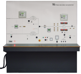


ELECTRICAL POWER SYSTEM SIMULATOR
Generator and grid supply
The PSS1 has a motor (prime mover) and generator set to simulate power generation. This set has characteristics similar to industrial turbine and generator sets for realistic experiments. The output of the generator passes through a generator transformer to a ‘generator bus’. Protection relays and circuit-breakers monitor and switch the generator field and output.
The PSS1 includes a fully monitored and protected grid supply transformer. This transformer simulates the larger grid transformers used in national grid supply systems. The grid transformer reduces the incoming mains supply to give the correct distribution voltage at the ‘grid bus’. It also allows students to correctly synchronise the generator output to the grid supply. For realistic tests, students can use the grid supply or the generator as a power source for their experiments.
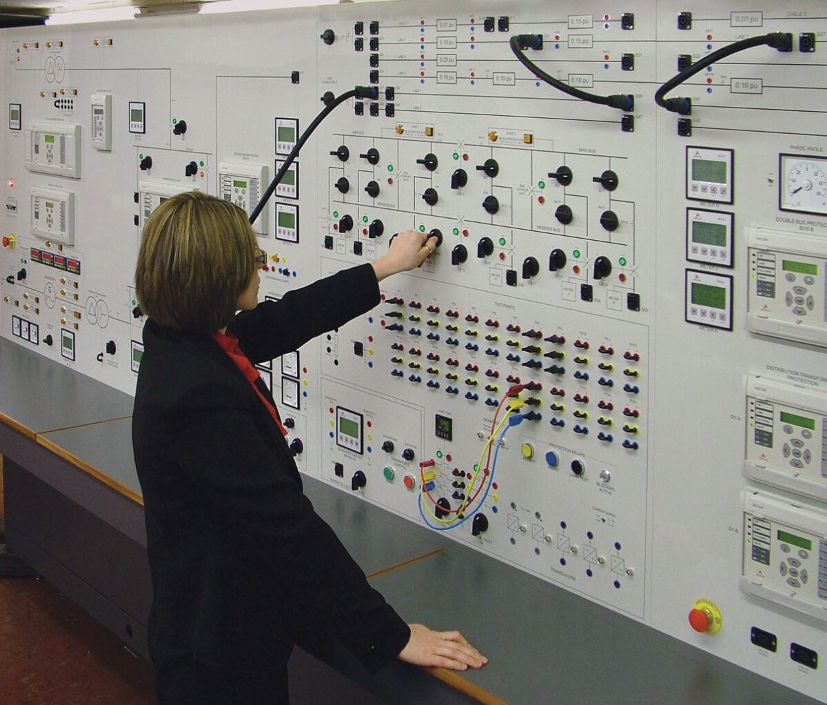
Transmission lines
A set of reactances simulate transmission lines of different lengths to model the characteristics of overhead or underground power cables. Each line includes test points to monitor the conditions along the lines. The user can simulate faults at different places along the transmission lines and discover the effects. A dedicated distance protection relay protects the lines and can indicate how far along the line the fault has occurred.
Transformation, distribution and utilisation
As well as the grid supply and generator transformers, the Electrical Power System Simulator has two identical distribution transformers to simulate the distribution transformers fitted near to factories or houses. These transformers have variable tappings and feed a ‘utilisation bus’. Dedicated relays protect the transformers and can work in different ways, determined by student experiments. The utilisation bus simulates electrical consumers (houses and factories). It includes variable resistive, capacitive and inductive loads, with an induction motor (dynamic) load.
A switched busbar section includes a main bus and a standby or ‘reserve bus’. These simulate a real busswitching system in a power plant or power distribution station. Protection relays and circuit-breakers monitor and switch the incoming and outgoing feeders of the busbar. One feeder of the busbar has a ‘point-on-wave’ circuitbreaker for studies of switching transients.
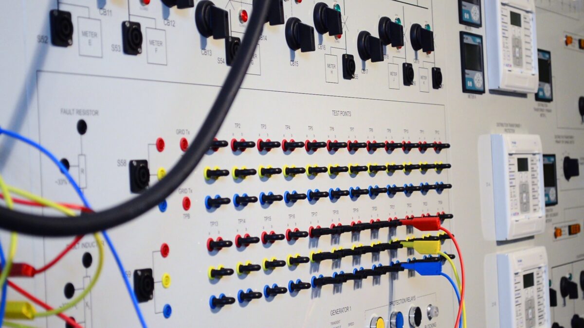
Test points, transducers and fault switches
All the important circuits have test points connected to a set of test sockets. The students can link out these sockets or connect them to other test equipment. A set of transducers allows students to connect the test sockets to an oscilloscope (supplied) for transient measurements.
There are two fault switches to apply faults to different parts of the Power System Simulator. One fault switch is a standard three-phase switch; the other is a timed circuit breaker with a user-programmable digital timer to set a precise fault duration.
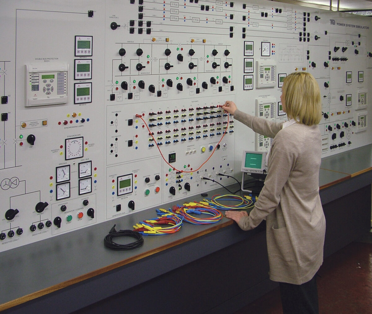
Protection relays, circuit breakers, blocking switches and instruments
All parts of the PSS1 include industrial-standard protection relays. The relays show students how actual power systems are protected and the different ways that they are protected. The students can set the relays from their control panels. The relays also include sockets to link them to a suitable computer for more detailed programming, if needed. The relays operate the circuit-breakers around the PSS1 for multiple experiments in protection. They also allow the user to try different methods of setting the operation of the relays, including:
- Auto-reclose
- Back tripping
- Directional tripping control
- Zone protection
- Protection grading
Blocking switches with warning lights allow the user to temporarily override the relay protection at key points, for enhanced experiments.
The circuit-breakers also include hand-operated switches, and lamps. The lamps show whether the circuit-breaker is open or closed.
Multi-function digital meters connect to all the important circuits to show the conditions of all three phases. A phase-angle meter shows the phase difference between any two voltages connected to it.
Moving coil meters show the prime mover voltage, current and power.
Learning outcomes
- Power transmission, distribution and utilisation
- Load flow, circuit interruption and differential protection
- Symmetrical, unsymmetrical and unbalanced faults and loads
- Generator synchronisation and performance, including stability and voltage regulation and control
- Using protection relays for overcurrent, distance protection, phase and earth faults
- Using protection relays for differential protection, under and overvoltage and frequency protection
- Transformer tappings and impedances
- Using relays for protection of a busbar, transformers and generators
-
 ELECTRICAL POWER SYSTEM SIMULATOR
Power Systems Trainer (PSS1) - TecQuipment