This blog post was written by Peter Mumford, who shares his knowledge and passion for sports science with an engineering perspective.
Wind tunnels provide a variable testing environment for bikes as well as cyclists in-situ, allowing for trial and error testing in order to tailor an aerodynamic strategy for a riders’ needs.
Aerodynamics of Cycling
At an elite level of cycling, aerodynamics are a significant contributing factor to performance, with the bike attributing between 31-39% of total aerodynamic drag, depending on rider position [1]. Aerodynamic efficiency of the cyclist is contributed to the resistive forces against the cyclist’s direction of motion (aerodynamic drag) as well as moments that resist wheel rotation.
There are three key determinants for improving aerodynamic efficiency: reducing cross-sectional area in the frontal plane, streamlining the bike geometry and reducing the surface roughness [1].
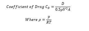
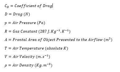
Where:
Rider Positioning & Bike Geometry
Cyclists generate large regions of separated flow, largely caused by the sharp edges of the shoulder blades combined with a rapidly reduced body width towards the trailing edge. The significant pressure gradient on the boundary layer prevents the flow from reattaching. Such separated flows infer that cyclists should be considered as bluff bodies. During the crank cycle there are large variations in aerodynamic drag as the legs move in the frontal plane, which brings challenges to developing the optimum aerodynamic position.
Frontal area ![]() is an incredibly important factor as the reduction to drag coefficient allows a rider to achieve a greater speed for the same power output (W). For example, a cyclist when positioned on the handlebar drops and seated on a conventional road bike measuring 175cm in height and a mass of 69kg would produce an approximate drag coefficient of 0.88
is an incredibly important factor as the reduction to drag coefficient allows a rider to achieve a greater speed for the same power output (W). For example, a cyclist when positioned on the handlebar drops and seated on a conventional road bike measuring 175cm in height and a mass of 69kg would produce an approximate drag coefficient of 0.88![]() . However, on a more streamlined time trial bike this would be estimated to be closer to 0.7
. However, on a more streamlined time trial bike this would be estimated to be closer to 0.7![]() for the same [2]. To enhance aerodynamic efficiency, bike frames typically have a teardrop-shaped head tube.
for the same [2]. To enhance aerodynamic efficiency, bike frames typically have a teardrop-shaped head tube.
Whilst this reduction in drag would make it seem vital to use a time trial bike, in a practical sense these bikes bring with them a significant reduction in comfort and stability and therefore would not be suitable for long distance, large group and/or technical course riding.
Wheels
In terms of drag coefficient, disc wheels are commonly found on time trial bikes and produce less frontal drag than a conventional spoke wheel. However, the caveat of this is a significant reduction in stability as it creates a barrier perpendicular to the wind. This creates challenges when cornering, so disc wheels should be limited to use on time trial bikes in still conditions on straight courses.
Helmets
A rider’s head position can have a significant impact on the net drag force to overcome based on the location of the head relative to the flow and head size relative to the whole cyclist-bike system [3]. Aero helmets, which also appear “teardrop-shaped”, have reported 7% lower drag than conventional round helmets [1], attributed to eliminating the gap between posterior of the head and upper back when seated on the bike, delaying separation and preventing recirculation of turbulent air [4]. Such aerodynamic efficiency means the drag coefficient would be greater in the absence of a helmet. Aero helmets come in a range of form factors to provide ventilation capabilities, safety features, head mobility and comfort for extended riding periods. However, such considerations can potentially compromise aerodynamic performance, although finding an optimal balance between aerodynamic performance and secondary factors may have a greater influence on cycling performance than fast and slow wheels [5].
Clothing Texture
Surface textures of a cyclist’s clothing have significantly progressed to reduce total aerodynamic drag ![]() . Current research suggests this can be detrimental to aerodynamic efficiency. Incorporating dimples into the cyclists’ clothing, similar to those on the surface of a golf ball which allow a ball to travel straighter and further, delay separation and induce relatively small vortices, creating a thin turbulent boundary layer close to the surface. This facilitates laminar flow from behind the ball, decreasing the wake size and therefore reducing. By delaying the separation point further towards the rear of the cyclist the wake size can also be reduced, increasing wake pressure and reducing the pressure drag component of the aerodynamic resistance [3].
. Current research suggests this can be detrimental to aerodynamic efficiency. Incorporating dimples into the cyclists’ clothing, similar to those on the surface of a golf ball which allow a ball to travel straighter and further, delay separation and induce relatively small vortices, creating a thin turbulent boundary layer close to the surface. This facilitates laminar flow from behind the ball, decreasing the wake size and therefore reducing. By delaying the separation point further towards the rear of the cyclist the wake size can also be reduced, increasing wake pressure and reducing the pressure drag component of the aerodynamic resistance [3].
The general consensus seems to show that an aggressively aerodynamic setup will reap a low drag coefficient and therefore have significant speed benefits. However, the rider’s other needs such as comfort in the saddle should not be neglected.
[6] TecQuipment User Guide AF1300/1450/1600j
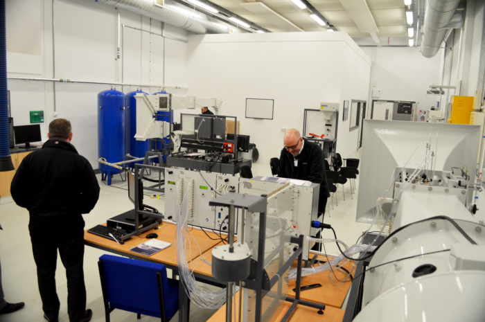
Wind Tunnel Testing using TecQuipment’s Aerodynamics Range
Wind tunnels aim to produce an environment that replicates the potential effects of various wind speeds. To accurately reflect outdoor conditions, the ratio between the combined projected frontal area of the bike and rider and the sectional area of the test room should be lower than 10 [7].
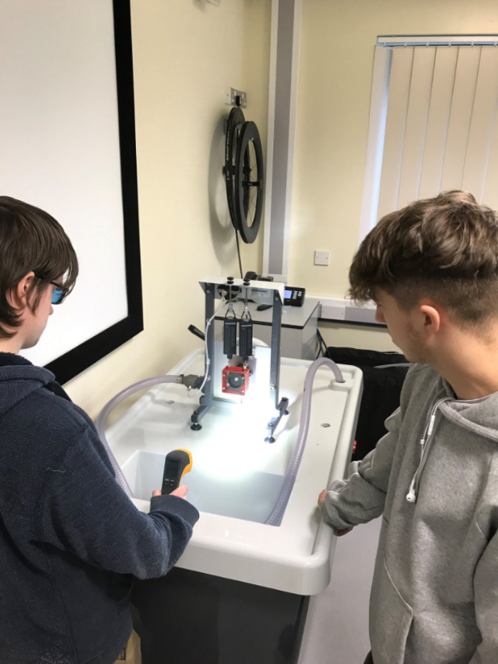
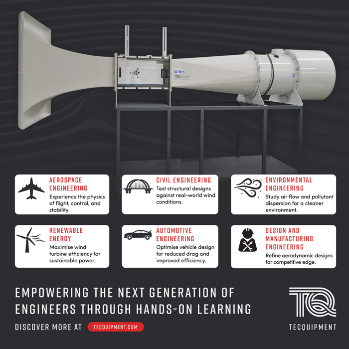
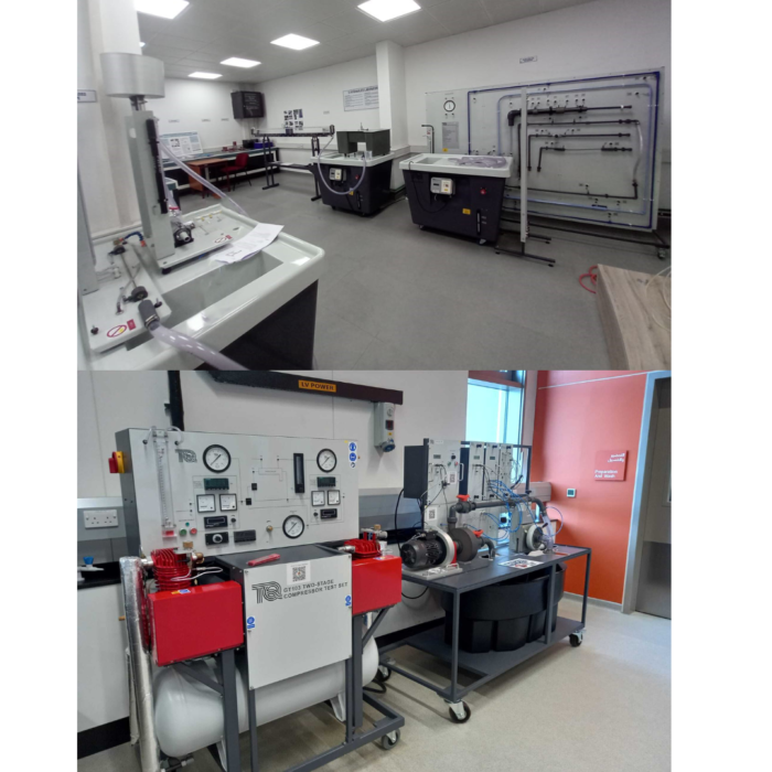
Whilst aerodynamic testing for a full-scale bike requires a large wind tunnel to operate, TecQuipment offers an equally effective scaled-down Subsonic Wind Tunnel (AF1300/ AF1450/ AF1600) apparatus which may be used with objects such as a bike helmet or a scaled-down model. Laboratory based wind tunnels are time and cost-effective alternatives, producing accurate results as long as scale effect and reduced Reynolds numbers are accounted for. Air enters the tunnel through an aerodynamically designed effuse (cone) that accelerates the air linearly. It then enters the working section and passes through a grille, which protects the fan from damage by loose objects, before moving through a diffuser and then to a variable-speed axial fan. The air leaves the fan, passes through a silencer unit and then back out to the atmosphere.
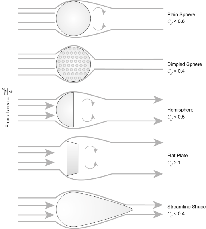
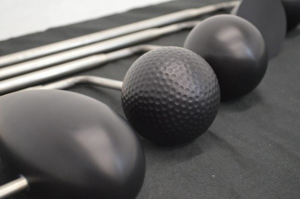
TecQuipment’s Three-Dimensional Drag Models (AF1300J/ AF1450J/ AF1600J) are compatible ancillaries to the subsonic wind tunnel range. All models have identical frontal surface area to allow students to compare the different coefficient of drag for each shape, including a dummy stem to cancel out the drag due to each model’s support arm. TecQuipment provide the following model shapes:
 Plain Sphere
- Dimpled Sphere (akin to a golf ball)
- Hemisphere
- Flat Plate
- Streamlined Shape ‘Teardrop’ (Based on a revolved NACA0040 aero foil)
For more information about the aerodynamics range of teaching equipment from TecQuipment click here.
Recommended Reads:
References
[1] Kyle, C.R. & Burke, E.R. (1984). Improving the racing bicycle. Mechanical Engineering, 106 (9), 34–35. [Accessed: 18th December 2019]
[2] Cycling Power Lab (2019). https://www.cyclingpowerlab.co... [Accessed: 18th December 2019]
[3] Crouch, T.N., Burton, D., LaBry, Z.A. et al. (2017). Riding against the wind: a review of competition cycling aerodynamics, Sports Engineering, 20: 81. [Accessed: 18th December 2019]
[4] R.A. Lukes, R.A, Chin S.B. and Haake S.J. (2005). The understanding and development of cycling aerodynamics, Sports Engineering, 59-74. [Accessed: 18th December 2019]
[5] Sidelko S (2007) Benchmark of aerodynamic cycling helmets using a refined wind tunnel test protocol for helmet drag research. PhD thesis, Massachusetts Institute of Technology [Accessed: 18th December 2019]
[6] TecQuipment User Guide AF1300/1450/1600j [Accessed: 18th December 2019]
[7] J.B Barlow, W.H. Rae, and A. Pope. Low-speed wind tunnel testing. John Wiley & Sons, (1999). Cited in Maier, Giulio, and Wilhelm Schneider. Sport Aerodynamics, Springer, 2009. [Accessed: 18th December 2019]