
Experiment
GT185
TWO-SHAFT GAS TURBINE
A self-contained fully instrumented educational two-shaft gas turbine that uses kerosene as the fuel. The experimental capabilities of this apparatus allows comprehensive investigations into the principles and performance of two-shaft gas turbines.


If you have any questions or you'd like to discuss a product, please call us.
+44 1159 722 611TWO-SHAFT GAS TURBINE
A self-contained, fully instrumented, educational two-shaft gas turbine. Powered by kerosene, the experimental abilities of this high-quality apparatus enable comprehensive practical investigations into the principles, and performance of two-shaft gas turbines.
This product helps students to understand the use of this ‘engine’ with a secondary power turbine, on practical applications such as helicopters or electrical power generators.
This is a popular choice for companies such as BAE System's Defence Information, Training and Services who uses this gas turbine equipment in Saudi Arabia.
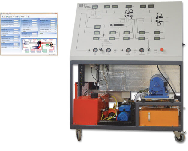
A steel frame holds a gas generator, power turbine, combustion chamber, oil and fuel tanks, pumps, ancillaries and guards. Above these is an instrumentation and control panel with schematic diagram. The clearly labelled control panel with mimic diagram includes the instrument displays, controls and warning lights.
Air passes through a calibrated nozzle and air box, into a compressor, then into the combustion chamber. A pump transfers fuel from the fuel tank to spray through a special nozzle into the combustion chamber. A high-energy spark ignites the air and fuel mixture, that flows to a gas generator turbine. The combustion chamber gives excellent combustion, low pressure loss and good flame stability over a wide range of conditions. A fuel flow control valve on the instrumentation and control panel regulates the turbine speed. This design reduces the possibility of overspeed.
Hot gas from the gas generator turbine passes through a short duct to the power turbine. The short duct reduces heat losses to atmosphere. The exhaust gases then discharge to a suitable exhaust system.
The power turbine couples direct to an eddy current dynamometer, so there are no belts to adjust. A load cell on the dynamometer measures torque and a sensor measures the dynamometer speed, to allow calculation of true shaft power. A control on the instrumentation and control panel adjusts the load of the dynamometer (and therefore speed of the power turbine).
The equipment has an oiling system including filters and water-cooled oil.
A PLC (programmable logic controller) controls the turbine start up and shut down. For protection of the equipment and user, it shuts down the turbines if the user makes an error. It also switches on cooling fans after running. Digital and analogue indicators show all the important readings from the sensors around the equipment, such as pressures, temperatures, fuel flow and level.
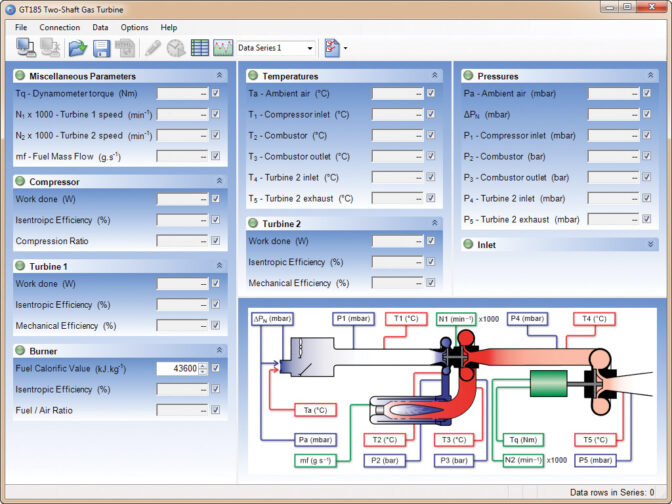
This equipment connects to your computer and includes specialist, user-friendly data acquisition software. This allows students to display, graph and analyse all relevant variables, and save their results for later analysis. The supplied data acquisition system includes a connection cable.
TecQuipment supply a detailed textbook with the equipment. The textbook covers the theory and use of gas turbines.
Learning outcomes
- Specific fuel consumption
- Pressure losses and ratios
- Thermal, isentropic and mechanical efficiencies
- Work and power
Experiment
GT100
TURBOJET TRAINER
Experiment
GT100RS