
Experiment
TM1021V

CAM ANALYSIS MACHINE
A machine to allow students to study the dynamic behaviour of different cams and followers and their "bounce" speed.


If you have any questions or you'd like to discuss a product, please call us.
+44 1159 722 611CAM ANALYSIS MACHINE
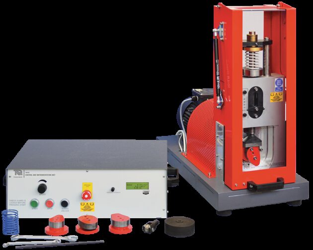
The TM1021 is a comprehensive machine that allows students to study cams and followers. It shows how they convert rotary to linear motion, and helps students understand their limits of use before the onset of ‘bounce’. It also introduces students to key topics of cam terminology such as ‘nose’, ‘flank’ and ‘dwell’.
The main part of the product has a precision machined heavy steel base which holds a high-torque direct-drive variable-speed motor. The motor shaft connects through a coupling to the main shaft which then passes into the cam test area. Self-aligning heavy-duty bearings support the shaft which has a substantial flywheel. The flywheel reduces speed variations as the torque demand changes during the cam rotation cycle. The cam under test fits to the end of the main shaft, accurately mounted both axially and radially to ensure repeatability.
The follower fits to the bottom of a vertical shaft running in low-friction linear bearings. TecQuipment include a tool for easy changeover of a choice of two followers. Students may also fit one of a choice of two compression springs and adjust their preload. These add to the mass of the follower and vertical shaft pushing the follower onto the cam face. Students may also add different masses (included) to alter the mass of the follower and thus the force applied to the cam. The selection of springs, followers and cams allow for a wide range of investigations.
Sensors on the main and vertical shafts measure angular position of the cam and vertical position of the follower (displacement or ‘cam lift’).
A key point of the design of the machine is safety while still allowing easy use. A fixed guard covers the shaft and flywheel. A hinged protective guard with electromechanical interlocks prevents users from touching any moving parts in the cam test area when in use. The guard opens only under safe conditions to allow students to change the cam, spring and follower.
A Control and Instrumentation Unit allows students to vary the cam speed. This unit amplifies and conditions the signals of follower vertical position (displacement) and cam angular position. It also includes a microprocessorcontrolled multiline display of cam speed in revolutions per minute, radians per second and rotational frequency in Hertz.
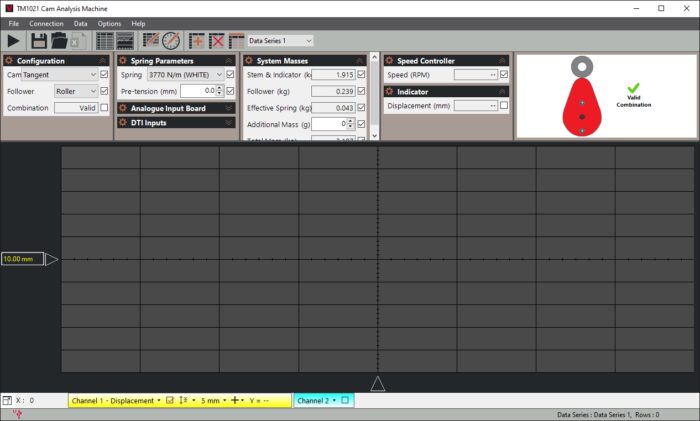
TecQuipment calibrate the conditioned signals of follower displacement and cam position to work with the Versatile Data Acquisition System, VDAS® (mkII). The VDAS hardware and software produce live displays of the follower displacement against cam rotation.
Uniquely, it also calculates and displays live plots of the first two derivatives of displacement - velocity and acceleration. The live plots alongside the characteristic ‘bounce’ sound allow students to find the speed at the point of cam bounce. They can then compare it to that found from simplified theory.
Learning outcomes
- Comparing actual results with theory for profiles of follower displacement, acceleration and velocity
- Cam bounce speeds for different cam and follower combinations, and comparison of speeds to those predicted by simplified theory
- How spring rate, preload and follower mass affect cam bounce speed
-
 CAM ANALYSIS MACHINE
Cam Analysis Machine - TecQuipment
Experiment
DefleX-2D
DefleX
Experiment
ES12