
Experiment
TM165

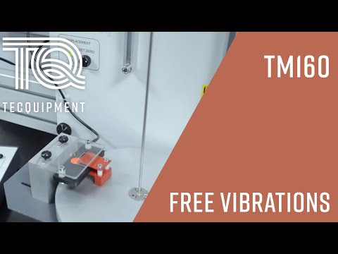
FREE TORSIONAL VIBRATIONS
An experimental apparatus that allows students to investigate the oscillatory motion of a disc attached to a slender rod.


If you have any questions or you'd like to discuss a product, please call us.
+44 1159 722 611Upgrade to package
FREE TORSIONAL VIBRATIONS
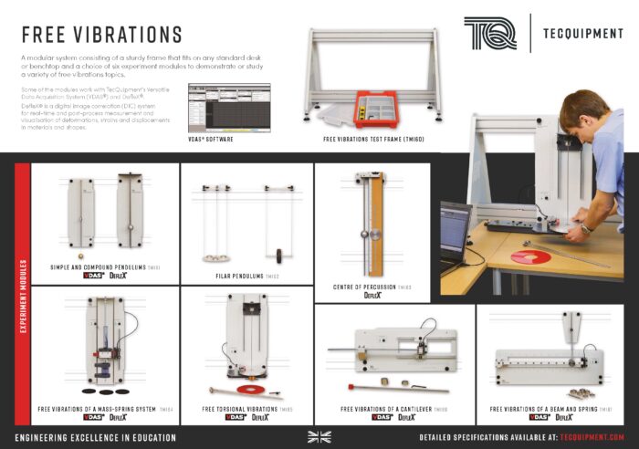
This product is part of a range that explores free vibrations in simple ‘one degree of freedom’ systems.
It introduces students to key scientific terms such as:
- Simple harmonic motion (SHM)
- Frequency of oscillation
- Shear modulus
- Polar moment of area
- Mass moment of inertia
- Phase difference between displacement and its derivatives
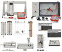
This product fits to the sturdy Test Frame (TM160) for study or demonstration.
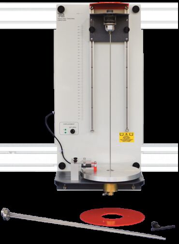
This product includes a rotating disc or ‘rotor’ at the end of a slender rod. You can compare this with the massspring system, except it replaces mass with the rotor’s mass moment of inertia and the spring with the twisting of the rod.
A back panel fixes to the Test Frame. The panel holds two vertical runners. The runners hold a chuck that securely grips a specimen rod at any position along its length. The bottom of the rod fixes to a rotor that is free to rotate. A bushing ensures the rotation remains along the axis of the rod, and supports the rotor during setup.
A non-contacting sensor next to the rotor disc measures the amplitude of the rotational oscillations. The sensor has no physical contact with the rotor, for negligible damping. The equipment includes a selection of rods of different diameter and the chuck position may be adjusted. A scale on the back panel referenced to the bottom of the rod gives a direct indication of the rod’s ‘effective’ length. Students can use these to discover how rod diameter and length affect the torsional oscillations.
Students may also fit an additional inertia disc to the rotor to see how the increased inertia affects the torsional oscillations.
Students lower the rotor support when ready and then gently twist and release the rotor to cause free torsional oscillations in the specimen rod. They then find the frequency of oscillation and compare it with that predicted from theory.
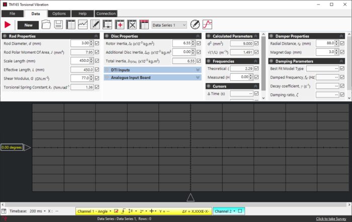
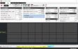
TecQuipment calibrate the displacement sensor to work with VDAS (mkII) for real-time display and data acquisition of system oscillation waveforms. Students use the software to see the displacement waveform and measure frequency. The software calculates and shows the first two derivatives of displacement - velocity and acceleration.
TecQuipment have specifically designed the TM165 to work with VDAS (mkII). However, the sensor output may be connected to your own data acquisition system or oscilloscope if desired.
Students may fit an optional Damper Kit (TM165a) to test how viscous damping affects the rotor oscillations. This kit includes a bracket that holds a powerful magnet above the rotor of the TM165. The magnet induces eddy currents in the oscillating rotor, opposing and damping its motion. The damping effect is proportional to velocity and becomes zero when the rotor stops oscillating. This makes it a form of viscous damping.
When using the Damper Kit, VDAS can fit its displayed data to under-damped viscous damping models.
Learning outcomes
- Rod diameter and frequency of oscillation
- Rod length and frequency of oscillation
- Inertia and frequency of oscillation
- Phase difference between displacement and its derivatives
- Damped torsional oscillations (needs optional Damper Kit)
-
 FREE TORSIONAL VIBRATIONS
Free Vibrations TM160 Series - TecQuipment
Experiment
DefleX-2D
DefleX
Experiment
DefleX-3D
DefleX
Ancillary
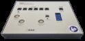
VDAS-B (mkII)
VDAS mkII (BENCH MOUNTED VERSION)

Ancillary
TM165A